Specification
| Primary Voltage (V) |
23000 |
| Model |
TR D3SP-15-23000-220y/127 |
TR D3SP-30-23000-220y/127 |
TR D3SP-45-23000-220y/127 |
TR D3SP-75-23000-220y/127 |
TR D3SP-112.5-23000-220y/127 |
TR D3SP-150-23000-220y/127 |
TR D3SP-225-23000-220y/127 |
TR D3SP-300-23000-220y/127 |
TR D3SP-500-23000-220y/127 |
| KVA Rating |
15 |
30 |
45 |
75 |
112.5 |
150 |
225 |
300 |
500 |
| No-Load Loss (W) |
90 |
126 |
170 |
240 |
315 |
360 |
520 |
660 |
1050 |
| Full Load Loss at 85°C (W) |
206 |
373 |
533 |
811 |
1144 |
1447 |
2144 |
2680 |
3972 |
| Total Losses at a load factor of 80% (W) |
222 |
365 |
511 |
759 |
1047 |
1286 |
7892 |
2375 |
3592 |
| 80% load for distribution transformers (Efficiency in % at 85°C) |
98.18 |
98.5 |
98.6 |
98.75 |
98.85 |
98.94 |
98.96 |
99.02 |
99.11 |
| Impedance (85°C) |
2.0~4.0 |
2.0~4.0 |
2.0~4.0 |
2.0~4.0 |
2.0~4.0 |
2.0~4.0 |
2.0~4.0 |
2.0~4.0 |
2.0~4.0 |
| Oil Weight (L) |
520 |
520 |
530 |
555 |
560 |
610 |
610 |
630 |
650 |
| Total Weight (KG) |
1500 |
1530 |
1560 |
1580 |
1750 |
1850 |
2180 |
2500 |
3100 |
| Dimension (mm) A |
2050 |
2050 |
2050 |
2050 |
2050 |
2050 |
2050 |
2050 |
2050 |
| B |
830 |
830 |
830 |
830 |
840 |
850 |
880 |
880 |
930 |
| ØD |
820 |
820 |
820 |
820 |
820 |
820 |
820 |
820 |
820 |
| H |
1900 |
1900 |
1900 |
1900 |
1900 |
1900 |
1900 |
1900 |
1900 |
| Winding Material |
AL-AL |
AL-AL |
AL-AL |
AL-AL |
AL-CU |
AL-CU |
AL-CU |
AL-CU |
AL-CU |
If you are interested in our transformers and related transformer accessories, please get more information and professional solutions through this website or directly through info@wishpower.net
What is the 25kV 3–phase Pad–mounted Transformer?
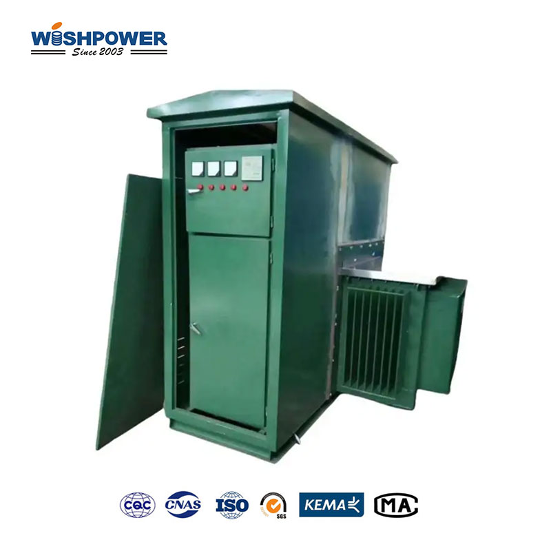
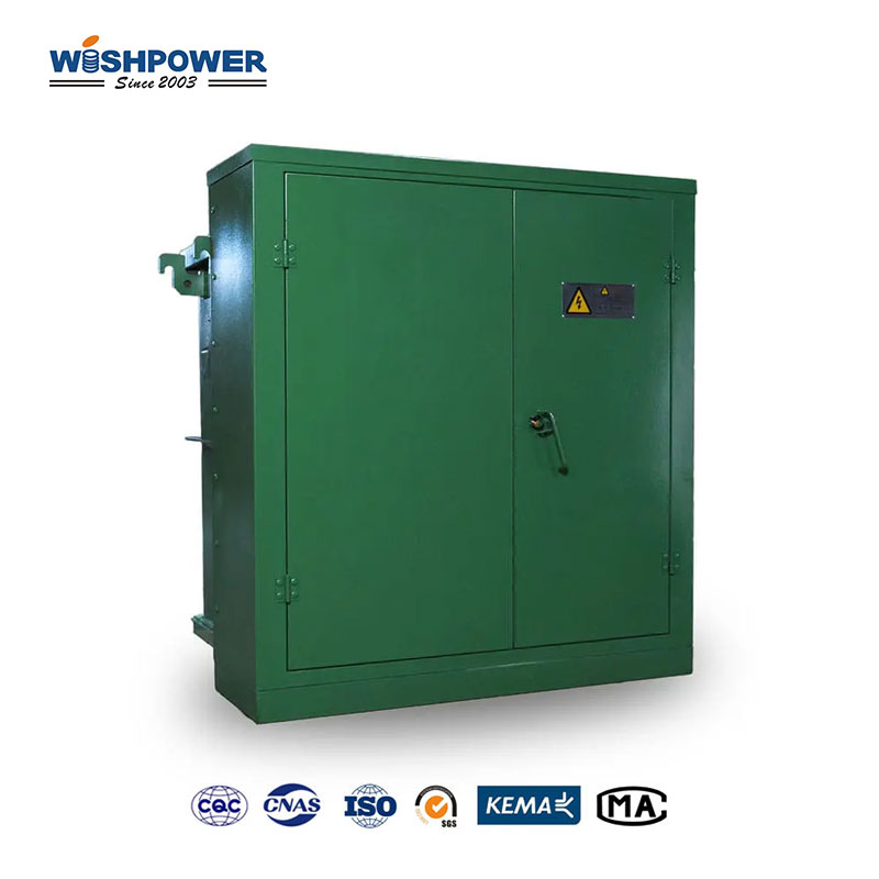
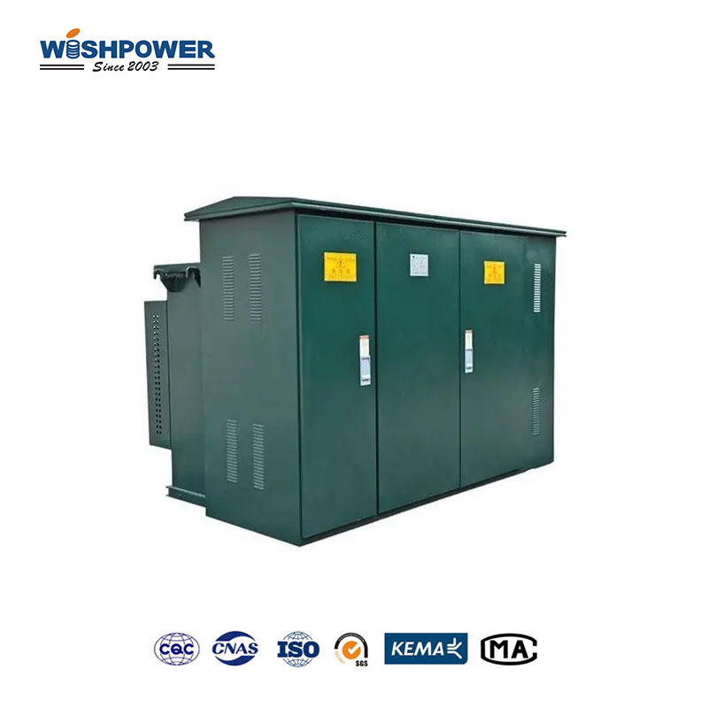
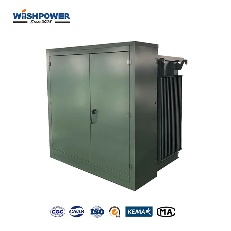
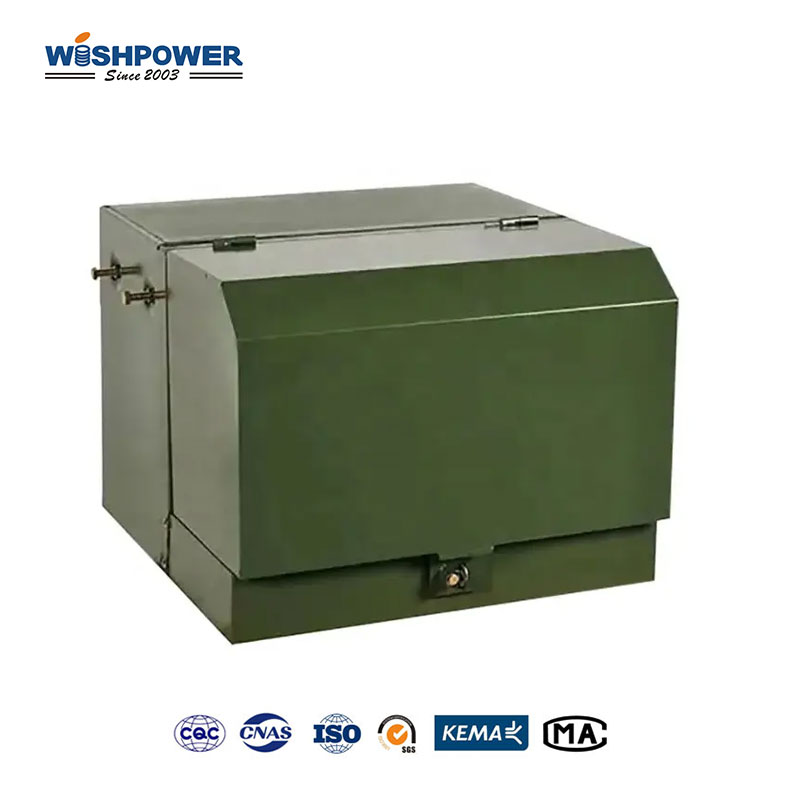
An electrical distribution transformer, which is represented by a 25kV 3-phase pad-mounted transformer, is used to step down power supplied to an electric grid into a lower more manageable voltage by the third party. It is a 3-phase transformer and is designed for high-power output situations like large buildings, industrial equipment, and some utilities. This is the right size for moderate power distribution needs. The pad-mounted design is one with the transformer located on a concrete or metal base, typically installed outdoors, and enclosed in a weather-resistant durable insulated cabinet. The transformer is protected from environmental elements such as rain, dust, and debris, as well as unauthorized entry into the equipment, in this design. The transformer works using electromagnetic induction to move high-voltage electricity coming in over to the lower voltage that goes out. Being a three-phase structure the energy can be transmitted efficiently and there is minimum wiring required to be done, which makes it very useful in case of a larger power load.
Transformer Size and Ratings
- Power Rating:
Rated Power: The transformer can take 25 kV (kilovolt), or am (the unit of apparent power). This rating indicates how much load the transformer can cope with without getting overheated and being worn out.
Phase Configuration: used for industrial, commercial, or larger residential uses that require more power, 3 phase means the transformer is meant to carry a balanced 3-phase load, and 3 phase systems are more efficient for higher power levels, and smoother operation than single phase systems.
- Voltage Ratings:
Primary Voltage: (Medium voltage) 12,000 V (typically). A 25kV pad-mounted transformer is available in common primary voltage ratings from 11kV to 15kV, depending on which grid configuration the utility operates with.
Secondary Voltage: For industrial equipment and commercial buildings the secondary voltage for the most common 25kV transformer is 480V. With different customer needs, the secondary voltages can be 208V, 240V, or other, and secondary voltages are quite common in other electrical systems as well.
Voltage Taps: Sometimes pad-mounted transformers have tap settings on the primary side (e.g., +2.5%, 0%, -2.5%) in order to give a slight variation in voltage to optimize the power delivery.
- Impedance:
Impedance: Typically between 2.5% to 5%. Transformer impedance plays an important role in short circuit behavior and voltage drop at load conditions. A transformer with low impedance has better short-circuit protection but is expensive.
- Frequency:
Frequency Rating: North American standard frequency is 60 Hz (Hertz). In other regions, the frequency is 50 Hz. Frequency rating is the alternate current (AC) cycle rate of the transformer.
- Efficiency and Losses:
Efficiency: Typically modern transformers ranging from 25kV or less are designed to be 98-99% efficient loaded. Efficiency is being a critical factor as it directly related to operating costs and energy consumption.
No-load Losses: They are losses when the transformer is energized but not supplying the load. Typical no-load losses for a 25kV transformer are about 50 to 150 watts.
Full-load Losses: When the transformer is supplying the maximum rated load, these losses occur. Full load losses for a 25kV transformer are between 1% and 2% of the rated capacity, or between 250 and 500 watts.
- Temperature Rating:
Ambient Temperature Range: Standard transformers are normally rated from -25°C to +40°C (ambient temperature range) to 65°C over ambient.
Insulation Class: The insulation Class normally used is Class 150 (allowing 150°C operating temperature of the insulation allowing the transformer to be operated in high high-temperature environment without damage).
- Cooling Type:
Cooling Type: ONAN (Oil Natural Air Natural) for pad-mounted transformers. In other words, the natural circulation of the oil and air is cooling the transformer. Oil helps from both an insulation and a cooling point, along with air circulation assisting with removing heat from the unit.
- Enclosure and Mounting:
Mounting Type: It is designed to be mounted on a concrete or metal pad, as a pad-mounted transformer and is an outdoor, space-constrained device.
Enclosure: The transformer is housed in a weatherproof steel cabinet intended to endure all kinds of rain, snow, and extreme temperatures. Incidentally, the enclosure ensures also safety by not allowing for access to live components other than at designated points of access.
Locking Mechanism: In general, a typical transformer will incorporate a locking system for access to prevent tampering or accidental contact between the transformer internals.
- Protection Features:
Overcurrent Protection: Pad-mounted transformers of 25kV or more are often equipped with some internal as well such as fuses or circuit breakers to protect the transformer from overloads and over excitation.
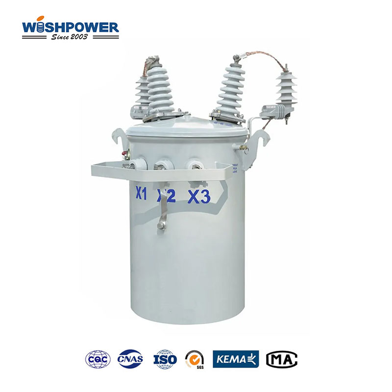
Bushing and Surge Arresters: Surge arresters are often provided with the transformer to prevent voltage rise in the event of lightning, or switching transient. Bushings are there to give a safe, insulated path for the electrical connections to go in and out of the transformer.
- Regulatory Standards:
Compliance: It is built by local and international standards like:
General transformer construction and performance, IEEE C57.12.00.
Pad-mounted transformers, ANSI C57.12.20.
International standards on transformer performance (a.k.a IEC 60076).
Are 25kV 3-phase Pad-mounted Transformers environmentally friendly?
Concerning materials, efficiency, and design features the 1 pad mounted transformer 3 phase 25 kV is an environmentally friendly transformer. Going one step further, polymeric insulation is used with biodegradable insulating oils, such as vegetable oils or synthetic esters, where a leak may be less harmful than a traditional mineral oil. This reduces potential incidents’ environmental impact. These transformers also perform at high efficiency, around 98–99%, which means that energy losses are minimized, there is less energy consumption and less carbon footprint is needed to produce that energy. In addition, to lead-free components, the transformers are environmentally friendly, due to the use of recyclable materials such as steel, copper, and aluminum which could be reused at the end of the transformers’ life. Moreover, these modern pad-mounted transformers are quieter than pole-mounted transformers, and cut down noise pollution, notably in places of habitation and urban areas. These transformers have a service life of about 20 – 40 years, and this can promote sustainable development in terms of reducing the frequency of replacement and minimizing waste.
Certificate
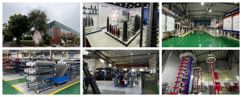
Factory
Hot Tags: 25kV 3-phase Pad-mounted Transformer, transformer, made in Thailand available, manufacturers, ISO factory, wholesale, KEMA, high quantity, best, price, low to high voltage


