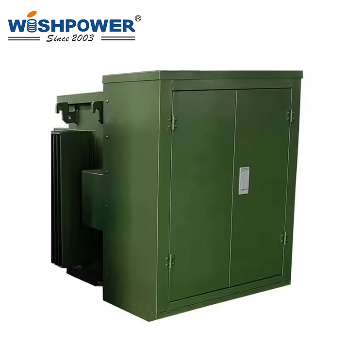
Specification
| Primary Voltage (V) |
13200 |
| Model |
TR D1-10-13200-120/240 |
TR D1-15-13200-120/240 |
TR D1-25-13200-120/240 |
TR D1-37.5-13200-120/240 |
TR D1-50-13200-120/240 |
TR D1-75-13200-120/240 |
TR D1-100-13200-120/240 |
TR D1-167-13200-120/240 |
| KVA Rating |
10 |
15 |
25 |
37.5 |
50 |
75 |
100 |
167 |
| No-Load Loss (W) |
60 |
75 |
106 |
142 |
137 |
203 |
235 |
275 |
| Full Load Loss at 85°C (W) |
82 |
120 |
181 |
253 |
362 |
426 |
564 |
1042 |
| Total Losses at a load factor of 80% (W) |
113 |
152 |
222 |
306 |
371 |
478 |
596 |
942 |
| 80% load for distribution transformers (Efficiency in % at 85°C) |
98.61 |
98.75 |
98.9 |
98.99 |
99.08 |
99.21 |
99.26 |
99.3 |
| Impedance (85°C) |
2.2~3.14 |
2.2~3.14 |
2.2~3.14 |
2.2~3.14 |
2.2~3.14 |
2.2~3.14 |
2.2~3.14 |
2.2~3.14 |
| Oil Weight (L) |
89 |
98 |
121 |
321 |
126 |
154 |
154 |
175 |
| Total Weight (KG) |
193 |
220 |
281 |
320 |
353 |
468 |
512 |
543 |
| Dimension (mm) A |
780 |
810 |
840 |
840 |
840 |
880 |
880 |
920 |
| B |
730 |
730 |
790 |
790 |
790 |
830 |
850 |
920 |
| ØD |
580 |
580 |
580 |
580 |
580 |
620 |
620 |
620 |
| H |
950 |
950 |
1000 |
1050 |
1070 |
1150 |
1180 |
1230 |
| Winding Material |
AL-AL |
AL-AL |
AL-AL |
AL-AL |
AL-CU |
AL-CU |
AL-CU |
AL-CU |
The table above is just one of our product parameters. If you want more information, please contact info@wishpower.net or download the file below.
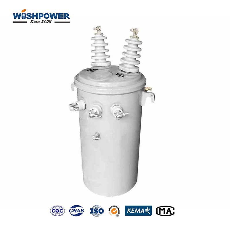
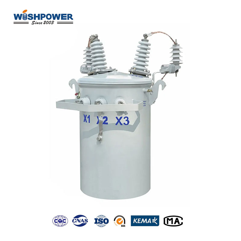
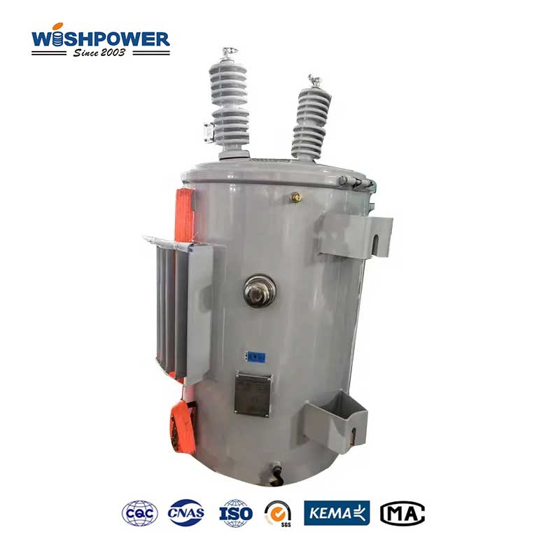
What is the Single Phase Pole Mounted Transformer?
The single-phase pole-mounted transformer is a simple type of electrical transformer that should be used for utility pole installation to supply electricity to residential, rural, and light commercial areas. Compact in size and lightweight built to handle single-phase power systems, such as for regions consuming low energy. This pole-mounted design allows space efficiency and easier maintenance access than ground-mounted options. The core structure comprises a laminated magnetic core and windings, which both work together to step down the high voltage from power lines to a usable voltage for end-user applications. The transformer is housed in a weatherproof steel or aluminum tank protecting components from the ravages of rain, Inclement weather, dust, and extreme temperatures. Some units are equipped with cooling fins to help in dissipation of heat, and to assure consistent operation. The transformers are manufactured in a combination of different safety and operational features, with bushings for more stable electrical connections, and surge protection against voltage spikes along pressure relief devices for greater safety. It used oil as a media of insulation, and cooling too, and allowed it to work more efficiently and longer. Eco-friendly, low-loss materials are commonly used in modern designs to meet energy efficiency standards and to minimize costs for operations.
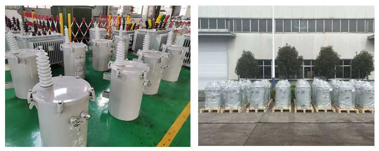
Single Phase Pole Mounted Transformer VS Three-phase transformers
Designed for areas requiring fewer available power outlets, such as e.g. residential neighborhoods, rural zone,s or isolated applications, single phase pole pole-mounted transformer is used. It reduces the voltage from distribution lines to the lower voltages on the order of voltages in small electric setups. With its lightweight and compact design, can be installed on utility poles, freeing ground space, simplifying maintenance, and facilitating. Field Testing In addition, single-phase transformers are cheaper for low-load applications and there is good efficiency for localized power distribution. Durability, environmental resistance, and easy configuration are stressed in their construction, which has made these appropriate for places with simpler power requirements.
In contrast, a Three Phase Transformer is a well-proven way of achieving high-capacity applications, like industrial plants, urban distribution networks, or large commercial facilities. This deals with the three-phase power systems that are commonplace in high power use locations due to their high efficiency in energy distribution, balanced load distribution, and lower required conductor materials. The three-phase transformers are usually big and bulky and are fitted on the ground or in substations. They are very suitable for handling higher loads and are critical for supplies of energy that are necessary and significant.
The main differences between them are functionality and the scale of application. Single-phase transformers are simpler in design and use than three-phase transformers as they cater to lower energy requirements and three-phase transformers are more complex and powerful in build, as they, utilize more power amounts. For cost-sensitive applications such as rural or residential projects requiring the basic power supply, single-phase units are cost-effective, whereas three-phase transformers provide higher efficiency and reliability in the higher demand applications.
Uptake of the Single Phase Pole Mounted Transformer is suited for applications of small scale, localized distribution, with the least cost of installation and maintenance whereas the Three Phase Transformer has better uptake for higher load industrial and urban sets up with its capability to carry out complex and energy consuming operations.
Pre-delivery test
- Type test
It shall comply with the requirements of GB/T 1094, GB/T 10228, GB/T 22072, GB/T 25446, GB/T 6451, and GB/T 311.1, and the short-circuit withstand capacity test shall be used as the type test. For oil-immersed transformers, the validity period of the type test report shall be by GB/T 1094.1. For dry-type transformers, the validity period of the type test report shall be by GB/T 1094.11. For dry-type transformers, environmental tests, climate tests, and combustion tests may be used as type tests according to the application.
- Routine tests
It shall include the following:
- a) Winding resistance measurement. Winding DC resistance unbalance rate: less than 2% between lines and less than 4% between phases (measured at the end of the lead-out bushing).
- b) Voltage ratio measurement and connection group number verification. Voltage ratio deviation: less than 0.5% for the main tap and less than 1% for other taps.
- c) Measurement of DC insulation resistance of winding to the ground and between windings.
- d) Partial discharge measurement (applicable to dry-type transformers).
- e) Externally applied voltage withstand test.
- f) Inductive voltage withstand test.
- g) No-load loss and no-load current measurement.
- h) Short-circuit impedance and load loss measurement.
- i) Insulating oil test.
- j) Sound level measurement.
- k) Pressure sealing test (applicable to oil-immersed transformers).
- l) Test of accessories and main materials (or provide test report).
- m) Line-end lightning full-wave impulse test (applicable to Class A high-quality equipment).
- On-site test
According to the relevant provisions of GB 50150:
- a) Insulating oil test.
- b) Measure the DC resistance of the winding together with the bushing.
- c) Check the voltage ratio of all taps.
- d) Check the three-phase connection group of the transformer and the polarity of the lead wire of the single-phase transformer.
- e) Measure the insulation resistance of the core.
- f) Measure the insulation resistance of the winding together with the bushing.
- g) AC withstand voltage test of the winding together with the bushing.
- h) Impact closing test at rated voltage.
- Sampling test
Should include the following:
- a) Winding resistance measurement.
- b) Voltage ratio measurement and connection group number verification.
- c) Winding to the ground and between windings DC insulation resistance measurement.
- d) Line end lightning full wave impulse test.
- e) External withstand voltage test.
- f) Induction withstand voltage test.
- g) No-load loss and no-load current measurement.
- h) Short-circuit impedance and load loss measurement.
- i) Insulating oil test.
- j) Temperature rise test.
- k) Pressure sealing test (applicable to oil-immersed transformers).
- l) Capacity test.
- m) Short-time overload capacity test.
- n) Short-circuit withstand capacity test. The no-load loss increment of amorphous alloy transformers after the short-circuit withstand capacity test shall not exceed 10%.
- o) Long-term overload test.
- p) Combustion performance test, the combustion performance level should reach the F1 level (applicable to dry-type transformers).
- q) Partial discharge (applicable to dry-type transformers).
- r) Sound level measurement (applicable to Class A quality equipment).
- s) External coating inspection. (Applicable to Class A quality equipment)
- t) Determination of transportation quality (applicable to Class A quality equipment).
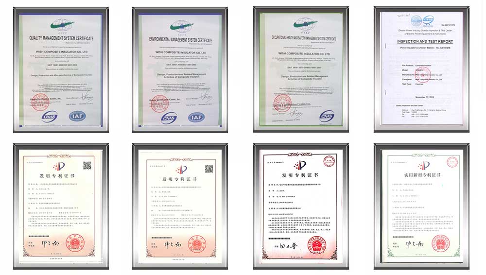
Certificate
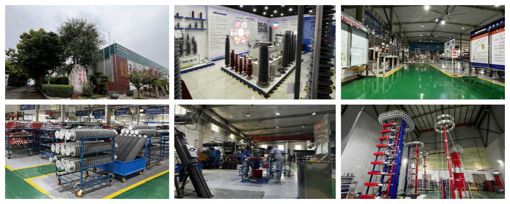
Factory
Hot Tags: Single Phase Pole Mounted Transformer, transformer, made in Thailand available, manufacturers, ISO factory, wholesale, KEMA, high quantity, best, price, low to high voltage


